티스토리 뷰
IDEC 강의 영상을 보고 정리한 내용입니다.
https://www.idec.or.kr/vod/apply/view/?pay=&search_val=CPU&no=273
반도체설계교육센터
강의제목 CPU 설계 및 응용 구분 부산대 / 설계강좌 / 초급/중급 / 이론+실습 강의시간 13시간 열람기간 16일 이용료(일반) 무료 이용료(학생) 무료 강의개요 SoC 설계를 위해서 CPU를 설계하고 응용할
www.idec.or.kr
저번까지 설계한 CPU의 구조이다.

이번에는 ALU를 설계할 것이다.
ALU
ALU는 CPU에서 실질적인 연산을 담당한다. 이번에 설계할 ALU는 사칙연산과 and연산을 할 수 있다.
이때 사칙연산은 adder를 기반으로 수행되기때문에 사실상 adder와 and로 구성되어있다. 또한 Brench 문을 수행하기위한 flag도 함께 구성되어야한다.

| Sign flag | AH<BREG(AH-BREG<0)이라면 1로 set됨. Sign flag = 1 => AH<BREG Sign flag = 0 => AH>BREG cf) AH=BREG => Sign flag = 0 |
| Carry flag | 덧셈(곱셈)이나 뺄셈(나눗셈) 연산에서 carry나 borrow가 발생하면 1로 set cf) overflow flag와는 다른 개념이다. |
| Zero flag | 덧셈결과가 0이고 carry가 발생하지않으면 1 뺄셈결과가 0이고 borrow가 발생하면 1 0을 판단하는 flag이다. |
참고로 overflow flag는 signed에서만 정의되는 개념이다.
Flag회로가 위와같이 나오는 이유를 알려면 하나하나 살펴봐야한다.
Sign flag
Sign flag는 둘중 무엇이 큰지 판별할 때 사용한다.

이 그림을 보면 왜 sign flag회로가 위와같이 구성되는지 알 수 있다.
Carry flag
Carry flag는 연산을 끝낸 후 오류가 있는지 확인하기위한 flag이다.
회로가 왜 저렇게 나오는지 알려면 Carry flag가 c_out(alu계산결과 carry)인가? 질문해보면 된다.
1. ADD
: alu carry = carry flag이다.
2. SUB
: sub연산의 결과는 양수와 음수 모두 가능하기때문에 carry flag가 의미 없다.
3. DIV
: 'SUB연산->carry보고 판단->연산'과정이 반복된다. 마지막 연산 과정에서 발생한 alu carry가 carry flag가 된다. 즉, alu carry = carry flag
여기까지 하면 다음과 같이 회로를 예상해볼 수 있다.

하지만 곱셈은 다르다.
4. MUL
: p_mul은 al_lsb와 and로 묶여있다. 즉, al_lsb가 0이라면 carry flag는 무조건 0이된다. al_lsb=0일 때 alu_carry가 1이 되는 는 상황을 찾으면 왜 and가 필요한지 알 수 있다. 그 이유는 다음과 같다.
ALU는 조합회로기때문에 alu carry가 저절로 갱신된다.
예시를 보기위해 1111x0110을 해보겠다.

ACC의 마지막 단은 DFF이고 ALU는 조합회로이므로 이전 ACC의 AH가 저절로 ALU에서 계산되어 Carry가 갱신된다. 4번 과정에서 빨간줄 친 부분이 저절로 계산되어 carry가 갱신된 부분이다. 이때 alu결과로 carry는 1이지만 carry flag는 0이어야한다. 이렇게 MUL 연산은 alu carry != carry flag인경우가 존재한다.
AL_LSB가 0이라면 무조건 carry flag=0이므로 p_mul과 al_lsb가 and로 묶여있다.

Zero flag
Zero flag는 계산결과가 0일 때 1로 Set된다.

회로는 다음과 같다. SUB의 경우 alu output이 0000이라면 무조건 0이다. SUB의 경우는 위의 회로가 맞다. 하지만 0+0의 경우 zero flag가 1로 변해야하지만 위의 회로는 변하지않는다. 따라서 수정이 필요할거같다. 일단 위의 회로대로 구현을 하겠다.
Register
Flag를 저장하기위한 1bit register이다.
module register(d,q,clk,clr,inen);
input d,clk,clr,inen;
output q;
reg st;

always@(posedge clk, posedge clr)
begin
if(clr) st = 1'b0;
else if(inen) st = d;
else st = st;
end
assign q = st;
endmodule
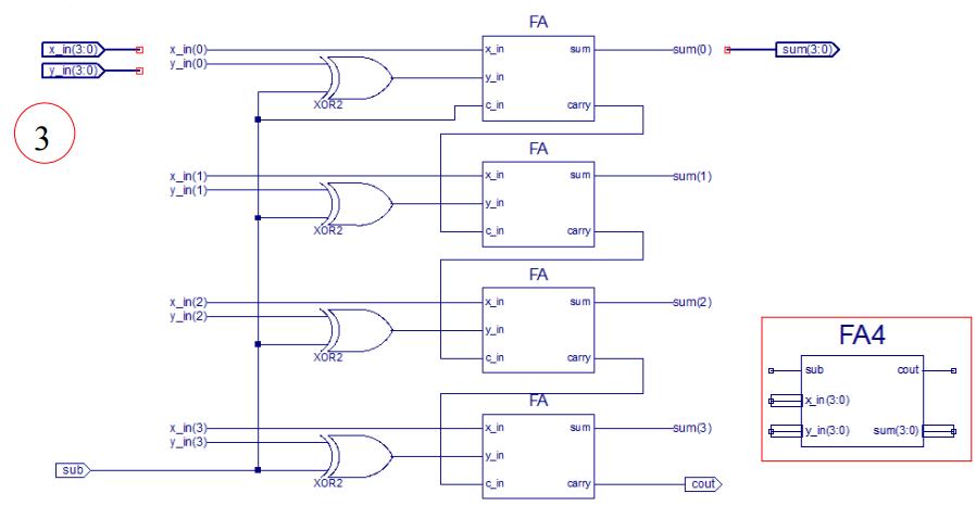
4 bit adder

module fa(c_in, x_in, y_in, sum, carry);
input c_in, x_in, y_in;
output sum, carry;

assign sum = x_in^y_in^c_in;
assign carry = (x_in&y_in&c_in)|(x_in&y_in)|(x_in&c_in)|(y_in&c_in);

endmodule
module fa4(x_in,y_in,c_in,sum,cout);
input [3:0] x_in;
input [3:0] y_in;
input c_in;
output [3:0] sum;
output cout;
wire c1,c2,c3;
//fa(c_in, x_in, y_in, sum, carry)
fa fa0(c_in, x_in[0],(y_in[0]^c_in),sum[0],c1);
fa fa1(c1, x_in[1],(y_in[1]^c_in),sum[1],c2);
fa fa2(c2, x_in[2],(y_in[2]^c_in),sum[2],c3);
fa fa3(c3, x_in[3],(y_in[3]^c_in),sum[3],cout);
endmoduleALU

module alu(alu_sub,alu_div,AH_in,BREG_in,alu_and, ALU_out,
Fa_cout,clk,clr,alu_add,alu_mul,al_lsb,sign_flag,carry_flag,zero_flag);
input alu_sub, alu_div, alu_and,clk,clr,alu_add,alu_mul,al_lsb;
input [3:0] AH_in;
input [3:0] BREG_in;
output [3:0] ALU_out;
output Fa_cout,sign_flag,carry_flag,zero_flag;
wire [3:0] a;
wire ze;
//module fa4(x_in,y_in,c_in,sum,cout);
fa4 fa4(AH_in,BREG_in,(alu_sub|alu_div), a,Fa_cout);
assign ALU_out=(alu_and)?(AH_in&BREG_in) : a;

//register(d,q,clk,clr,inen)
register SIGN_F((!(Fa_cout)&alu_sub),sign_flag,clk, clr,alu_sub);
register CARRY_F(((alu_add|alu_div|(alu_mul&al_lsb))&Fa_cout), carry_flag,clk,clr,1'b1);
assign ze=(a)?1'b0 : 1'b1;
register ZERO_F(ze,zero_flag,clk,clr,alu_sub);
endmodule
Simulation 검증
1. 값 검증
`timescale 1ns / 1ps
module tb_alu;
reg alu_sub, alu_div,
alu_and,clk,clr,alu_add,alu_mul,al_lsb;
reg [3:0] AH_in;
reg [3:0] BREG_in;
wire [3:0] ALU_out;
wire Fa_cout,sign_flag,carry_flag,
zero_flag;
alu UUT (alu_sub,alu_div,AH_in,
BREG_in, alu_and,ALU_out,
Fa_cout,clk,clr, alu_add,
alu_mul,al_lsb,sign_flag,carry_flag,zero_flag);
always #50 clk=~clk;
initial begin
AH_in=4'b0101;
BREG_in=4'b0010;
alu_sub=0;
alu_div=0;
alu_and=0;
alu_mul=0;
alu_add=0;
al_lsb=0;
clk=0;
clr=1;
#100; clr=0;
#100; alu_add=1;
#100; alu_add=0; alu_sub=1;
#100; alu_sub=0; alu_and=1;
#100; alu_and=0;
end
endmodule
조합회로이기때문에 클럭에 동작하지 않는 것을 알 수 있다.
2. Flag 검증
`timescale 1ns / 1ps
module tb_alu_flag;
reg alu_sub, alu_div,
alu_and,clk,clr,alu_add,alu_mul,al_lsb;
reg [3:0] AH_in;
reg [3:0] BREG_in;
wire [3:0] ALU_out;
wire Fa_cout,sign_flag,carry_flag,zero_flag;
alu UUT (alu_sub,alu_div,AH_in,
BREG_in, alu_and,ALU_out,
Fa_cout,clk,clr, alu_add,
alu_mul,al_lsb,sign_flag,carry_flag,zero_flag);
always #50 clk=~clk;
initial begin
AH_in=4'b0101;
BREG_in=4'b0010;
alu_sub=0; alu_div=0;
alu_and=0;
alu_mul=0;
alu_add=0;
al_lsb=0;
clk=0; clr=1;
#100; clr=0;
#100; AH_in=4'b0000;
BREG_in=4'b0000; alu_add=1;
#100; alu_add=0; AH_in=4'b0101;
BREG_in=4'b1010; alu_sub=1;
#100; BREG_in=4'b0101;
#100; alu_sub=0;
end
endmodule
나머지는 잘 되었지만 0+0일 때 zero flag가 0이다. 그 외에는 문제가 없다.
결론

현재 ALU까지 만들었다. 다음엔 ACC와 ALU를 연결하여 MUL과 DIV를 할 수 있는 회로를 만들것이다.
참고자료
- IDEC강의
'프로젝트 > 4bit CPU' 카테고리의 다른 글
| [4bit CPU #6] control unit(2) (control block) - 18EE (0) | 2023.07.21 |
|---|---|
| [4bit CPU #5] Control unit(1) (Decoder / Ring counter) - 18EE (0) | 2023.07.17 |
| [4bit CPU #4] ALU+ACC (feat.MUL/DIV) - 18EE (0) | 2023.07.16 |
| [4bit CPU #2] ACC(Universal shift register) - 18EE (0) | 2023.07.12 |
| [4bit CPU #1] Register, Program Counter(PC) - 18EE (0) | 2023.07.12 |
- Total
- Today
- Yesterday
- VTCMOS
- data gating
- 굿노트 mp3 내보내기
- MTCMOS
- dynamic power
- power gating
- 4bit CPU
- CMOS power
- VLSI dynamic power consumption
- DVFS
- Verilog
- 4bit
- vlsi
- mp3파일 추출
- CPU
- clock gating
- acc
- Control Unit
- level shifter
- 굿노트 내보내기
- ALU
- 굿노트 mp3파일 추출
- 굿노트 녹음파일
- VLSI 전력소모
- delay
- VLSI power
- static power
- Stack effect
- leakage
- switching power
| 일 | 월 | 화 | 수 | 목 | 금 | 토 |
|---|---|---|---|---|---|---|
| 1 | 2 | 3 | 4 | 5 | 6 | 7 |
| 8 | 9 | 10 | 11 | 12 | 13 | 14 |
| 15 | 16 | 17 | 18 | 19 | 20 | 21 |
| 22 | 23 | 24 | 25 | 26 | 27 | 28 |
